FPGA design with Verilog
California State Polytechnic University, Pomona
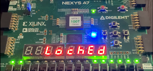
As part of the final project in my Verilog class, I designed a lock-unlocking program using the concept of a state diagram. Composed from the aggregated working of various components within the FPGA board — switches, RGB LED, 7-segment displays, buttons, and sound outputs.
Summary: The user sets a passcode using a binary string of switches; once confirmed, the program goes into a Locked state. Depending on the future response of inputs, the program decides whether to Unlock (passcode was successfully guessed) or let the user know an incorrecct attempt was made.
Tools: Digilent Nexys A7-100T FPGA Board, Verilog, Xilinx Vivado.


